Introduction
The Brewer Spectrophotometer is a scientific instrument which
measures Ultra Violet, or Visible, radiation in the solar spectrum.
By examining the differential absorption of select wavelengths in
the UVB portion of the spectrum, determinations of Total Column
Ozone and Total Column Sulpher Dioxide are inferred. In addition,
especially with the MKIII double monochromator instrument, accurate
spectral intensity profiles of UV radiation in the 286.5 nm to 363 nm
range are measured. The the MKIV instrument measures intensity of
radiation in the visible part of the spectrum (430-450nm) and uses
differential absorption in this region to infer Total Column Nitrogen
Dioxide.

|
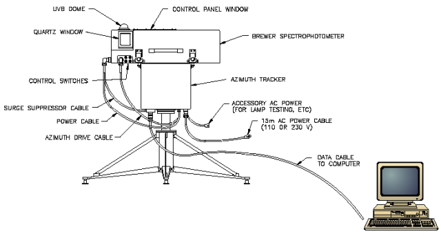
Brewer System Cabling
|

|
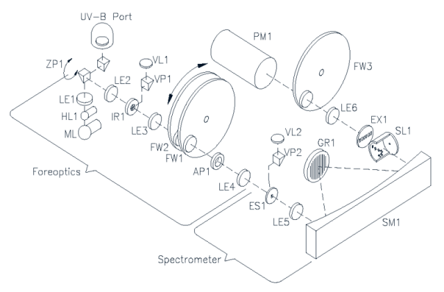
Brewer Optics Schematic Diagram
|

|
Brewer Mechanical Assembly (top view)
|
Internal Lamp Assemblies
A quartz-halogen lamp [HL 1] provides a well-regulated light source which is used
as a reference for sensitivity measurements. The lamp is powered by a constant
current source of nominal value 1.5 A, held to within 0.5% over a temperature range
of -20o to +40o C. The intensity of the radiation from the lamp under these
conditions is stable to within 5%. The filament of the lamp is placed at the focal
point of a double-convex lens [LE 1] so that the light from the lamp is directed along
the optical axis by the zenith prism.
Beneath the halogen lamp is a mercury discharge lamp [ML 1], which provides a
line source for wavelength calibration. Ultraviolet radiation from the mercury lamp
passes through the halogen lamp to the zenith prism. While the actual light
intensity of the lamp is not critical (a variation of 50% over the operational
temperature range is normal), it must remain stable to within 5% for short time
periods (10 minutes).
Foreoptics
The automated system drives stepper motors which control three elements
in the foreoptics assembly - the Iris Diaphragm, Filterwheel #1, and
Filterwheel #2. The associated driving and sensing electronics are
integrated into the Main Electronics board. The Brewer software
automatically controls motors once the Configuration File has been
appropriately configured. Incoming light is directed through the
foreoptics by the director prism [ZP 1], which may be rotated to
select light from either the zenith sky, the direct sun, or one of the
two calibration lamps. A mercury lamp provides a line source for
wavelength calibration of the spectrometer, while a quartz-halogen
lamp provides a well regulated light source so that the relative
spectral response of the spectrometer may be monitored. Elements
in the foreoptics provide adjustment for field-of-view, neutral-density
attenuation, ground-quartz diffusion, and selection of film polarizers.
Iris Diaphram Assembly
An iris diaphragm [IR 1] is mounted in the foreoptics at the ultraviolet
focus of a plano-convex lens [LE 2]. This lens focuses ultraviolet
objects at infinite distance onto the plane of the iris. A lever arm
which protrudes through the wall of the foreoptic tube controls the iris.
At one limit of the lever arm the iris aperture is 5mm ( iris closed),
while at the other limit the aperture is approximately 15mm (iris open).
The lever is actuated by the iris stepper motor. When the instrument is
aligned to view sunlight, an image of the sun is focused at the center
of the iris. With the iris closed, about three solar diameters of skylight
around the sun pass through the iris aperture into the spectrometer.
With the iris open, about 10O of skylight enters the spectrometer.
On the spectrometer side of the iris there is another plano-convex lens
[LE 3]. This lens is positioned such that its focal point is in the
plane of the iris. Light passing through the iris aperture is therefore
collimated along the optical axis. Lenses [LE 2, LE 3] in the
iris-diaphragm assembly are mounted with their plane side facing the iris.
Filterwheels
Filterwheels [FW 1, FW 2] are mounted on bronze bearings in a
filter-wheel housing. Each wheel has six 25.4mm diameter holes spaced
at 60 degree intervals. Each hole can be selected to intersect the
optical axis by rotating its filterwheel. The filterwheels are rotated
by two microprocessor controlled motors. FW #1 contains one open hole
( #3 ), two film polarizers ( #0 and #5 ), a groundquartz disk ( #1 ),
an opaque blank ( #2 ) and a second ground quartz disk + a neutral
density filter ( #4 ). The ground-quartz disk is used as a diffuser
for directsun and lamp measurements. The opaque disk is used for dark
count tests. The film polarizer ( #0 ) is used for all zenith sky and
Umkehr measurements. This film polarizer is mounted such that its axis
is perpedicular to the entrance slit. The second film polarizer ( #5 )
is mounted such that its axis is parallel to the entrance slit.
It is presently used only for specialized research purposes.
The open position (#3) is used for moon and UV observations.
The second ground quartz / N.D. filter is used in the NO2 mode of operation.
FW #2 contains an open hole ( #0 ) and five neutral-density filters providing
ND=0.0, 0.5, 1.0, 1.5, 2.0 and 2.5 attenuation ( #0 through # 5 ). This filterwheel is
used to automatically adjust the light level entering the spectrometer.
[AP 1], an 11.18mm fixed aperture located on the spectrometer side of the
filterwheel housing limits the field-of-view of the spectrometer to f/6.
Both Filterwheels have black markings that are visible through the viewing
window. The number of markings indicate the position of the filter wheel (positions 0
through 5).
Foreoptic Viewing Ports
There are two viewing ports along the foreoptic assembly, through which may be
viewed the iris diaphragm and any images which are focused onto it, and the
entrance slit. At the bottom of each viewing port is a glass right-angle prism
[VP 1, VP 2] mounted inside the foreoptic tubing. The prisms are aligned so that
the object to be viewed (iris or entrance slit) appears centred in the viewing port.
A plano-convex glass lens [VL 1, VL 2] is placed in each viewing tube to magnify
the image.
Rear Fore-Optics
A plano convex lens [LE-4], whose plane suface faces the entrance slit of the
spectrometers focuses the collimated ultraviolet radiation onto the entrance slit of
the spectrometer.
Spectrometer
The purpose of the spectrometer optical subassembly is to accept light through the
entrance slit and disperse it into a high-quality spectrum along the exit-slit focal
plane. The spectrometer is a modified Ebert type with focal length 16 cm, and
aperture ratio f/6.
Six exit slits are positioned along the exit focal plane at the Ozone (or NO2)
operating wavelengths - 303.2 nm (302.1 for mercury-wavelength calibration),
306.3/431.4 nm, 310.1/437.3 nm, 313.5/442.8 nm, 316.8/448.1 nm and 320.1/453.2
nm with 0.6/0.9 nm resolution. Wavelength is adjusted by rotating the grating with a
stepper motor which drives a micrometer acting on a lever arm. The wavelengthcalibration
procedure is capable of measuring the wavelength setting with a
precision of 0.0001 nm, and of controlling the wavelength setting to 0.006 nm.(in the
UV region.
At the exit of the spectrometer is a cylindrical mask which exposes only one
wavelength slit at a time. The mask is positioned by a stepper motor which cycles
through all five operating wavelengths, approximately once per second.
Spectrometer Detailed Description
Light enters the entrance slit and passes through a tilted lens [LE 5] which corrects
for the coma and astigmatic aberrations inherent in an Ebert system. The light is
collimated by a spherical mirror onto a diffraction grating where it is dispersed. A
second mirror reflection focuses the spectrum onto the focal plane of a slotted
cylindrical slit mask positioned at the exit of the spectrometer. After wavelength
selection by the slit mask, the light passes through the exit slit plate. Six exit slits
are located along the focal plane at the appropriate wavelength positions.
Entrance and Exit Slit Plates
The entrance slit and six exit slits [ES 1, EX 1] are etched into 0.1-mm-thick disks of
hard shim steel. One of the six exit slits (slit #0) is used for wavelength calibration
against the 302-nm group of mercury lines; the other five are for intensity
measurements and are nominally set at 306.3/431.4, 310.1/437.3, 313.5/442.6,
316.8/448.1, and 320.1/453.2 nm. The dimensions for the entrance and exit slits
are listed in the Selected Parts List.
Both slit plates are positioned on their respective housings by locating pins which
orient the slit axis to within 0. 1o. Both plates are blackened to minimize light
reflections.
Correction Lens
The correction lens [LE 5] has a convex-cylindrical surface (radius 170.0 mm) and
a concave-spherical surface (radius 230.0 mm).
Both surfaces are coated with a layer of magnesium fluoride to minimize
reflectance at 315.0 nm for an incidence angle of 29o. The lens is mounted in the
entrance-slit housing at an angle of 29o to the optical axis with the concavespherical
surface facing the entrance slit. The axis of the cylindrical surface is
positioned in the horizontal plane to within 1o.
Spherical Mirror
The spherical mirror [SM 1 ] has a 324 mm radius-of-curvature. The spherical
surface is ground from a rectangular pyrex blank. The surface is polished, coated
with aluminum, and then coated with magnesium fluoride to maximize reflection at
315.0 nm.
Spring-loaded mounts secure the spherical surfaces of the mirrors against three
adjustment screws which are normal to the spherical surfaces in the horizontal
plane of the spectrometers. The mirrors are allowed to move on a spherical surface
defined by the three adjustment screws, up to a limit of 0.25 mm in the horizontal
and vertical. Nylon screws prevent the mirrors from moving beyond this limit.
Diffraction Grating
The diffraction grating [GR 1 ] is a 1200 line / mm holographic plane-reflectance
type, operated in the third order in the UV for ozone measurements, and in the
second order in the Blue region. The grating has optimum efficiency over the range
225 to 450 nm in the first order.
The grating is secured with high-quality adhesive to three small blocks which
provide kinematic mounts, as well as fine adjustment for rotation of the grating
about the two axes perpendicular to the grating grooves. The three blocks are thus
part of the grating and are the basis of point, slot, and plane mounts which allows
adjustment by three screws fixed in the grating-mount plates. These plates are
suspended on a set of cross-springs which constrain the gratings to rotate in the
vertical axis (the axis parallel to the grating grooves). The cross-spring suspension
acts as a frictionless bearing. Rotation of the grating is controlled by two
micrometers acting at the end of lever arms such that a 0.03 mm adjustment of the
micrometers represents approximately a 0.1 nm wavelength change at the exit-slit
plane.
Micrometer
A metric micrometer head, clamped to the spectrometer frame is used to adjust the
grating rotation. The micrometer shaft is ground to a 60 degree cone which inserts
into a bearings at one end of a floating pushrod.. A conical depression with a
tetrahedral corner at the other end of the pushrod locates a 60-degree cone
mounted on the end of the grating lever arm. The pushrod is secured between the
micrometer shaft and lever arm by a tension spring. The material of the pushrod
has been selected to minimize differential temperature effects.
The micrometer is rotated by a stepper motor . The motor drives a 10-tooth gear
which is kinematically linked to a 60-tooth gear on the micrometer shaft. The drive
shaft is coupled to the motor shaft with a universal joint
One motor step represents 0.006 nm on the exit-slit plane (in the UV region).
Backlash of the micrometer and cross-spring bearing system has been measured at
0.002 nm.
Slit Mask Assembly
Located at the exit of the spectrometer is a slotted cylindrical mask which may be
located in one of eight positions Six of the eight positions allow light to enter one of
the six exit slits. The second mask position blocks light from all slits so that a dark
count measurement can be made. The eighth mask position exposes two of the exit
slits so that the dead time of the photon counting system may be determined. The
correspondence between slit mask position and selected wavelength is summarized
in Table 2-4.
The axis of the cylinder is attached to the shaft of a stepper motor. The mask is
aligned with the exit slits by adjusting the vertical position of the motor and adjusting
the horizontal position of the cylinder on the motor shaft.
By rotating the slit mask, each of the mask slots aligns with a corresponding slit in
the exit plane, effectively selecting a single wavelength. During an HG test the first
slot in the slit mask aligns with the Hg calibration slit in the exit plane.
Filter Wheel #3 Assembly (FW#3)
Light emerging from the exit slits passes through Filter Wheel #3 which contains
Spectral 'Order' filters. When the Brewer is in the Ozone Mode, a UG-11/NiSO4
filter combination prevents radiation above 325nm from passing. In the NO2 mode
of operation, a BG-12 filter blocks UV radiation.
During a UV measurement FW#3 switches from the a UG-11/NiSO4 filter
combination to a UG-11 filter at 325nm.
The Filter Wheel is driven by a stepper motor when appropriate commands are
received from the Brewer software.
Photomultiplier Detector (PMT)
Light passing through the exit slits is collected on the cathode of a low-noise EMI
9789QB05 PMT detector [PM 1]. The photon pulses are amplified, discriminated,
and divided by 4, before being transmitted to a counter. The resulting photon count
is registered in one of six wavelength channels.
Radiation through the exit slits is focused onto the cathode of the PMT by a 38.1
mm focal-length quartz Fabry lens [LE 6].
The cathode of the PMT is located at the ultraviolet focus of the Fabry lens. The
spacing between the lens and the PMT takes into account the apparent change in
focal length due to the presence of the filters. The PMT is enclosed in a magnetic
shield which is maintained at cathode potential (approximately -1300 V) to minimize
dark noise. The PMT and its shield are spring-loaded against a teflon ring which
locates the cathode at the center-of-focus of the Fabry lens and also insulates the
magnetic shield from the PMT housing.
The housing has been designed to allow access to the photon amplifying and
discriminating circuitry without disturbing the optics.
ULTRA VIOLET DOME ASSEMBLY
The UV Dome Assembly is an optical assembly which enables the Brewer to
measure global UV-B, and portions of UV-A and UV-C, using a thin disc of teflon
as a cosine collector. The disc is mounted on top of the instrument under a 5-cm
diameter quartz dome, and is thus exposed to the global UV irradiance. Beneath
the disc is a fixed reflecting prism which is located such that the disc is in the
spectrometer field-of-view when the zenith prism is set for a zenith angle of -90o.
Figure 2-3 shows an end view of the foreoptics with the UV subassembly in place.
SOLAR TRACKING
Zenith Positioning System
The Zenith positioning system is attached to the front end of the Foreoptics.
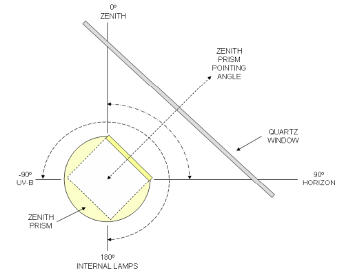
The prism has 270 degrees of rotation as shown in the Figure below. In the 180
degree position, the Zenith Prism faces the two internal lamps for SL and HG
measurements. In the -90 degree position, the Zenith Prism is directed towardsthe
UB-B dome for diffuse UV measurements. During Zenith Sky and Umkehr measurements,
the Zenith Prism is positioned vertically at the 0 degree zenith.

|
|
Zenith Prism (Side View)
|
Azimuth Positioning System
The Azimuth Tracker is an all-weather positioning pedestal comprised of a
weatherproof chassis which houses a stepper motor, drive electronics, and a
gearing mechanism. The tracker chassis is mounted on a Tripod assembly and is
levelled by means of adjustments on each tripod leg.
Between the Spectrophotometer and the Tracker is a control cable which carries
positioning commands from the Brewer electronics. The positioning commands are
input to a motor driver, which provides drive for a stepper motor. As the motor
rotates, it turns a stainless steel vertical shaft which, in a friction contact, rotates an
aluminum plate fixed to the rotational body of the tracker. The Tracker is fitted with
an optical sensor which is used as a reference point, and a 'Safety Switch' which
removes power to the motor in the event that a failure occurs in the reference
sensing system. The Tracker is fitted with its own power supply and power switch.
|