
Figure 5. TSI platform framework. Moved to opposite side for final install.

An adaptable structure suitable for the remote field site
Dennis Wellman and Gary Hodges
Abstract
A working field site in the often harsh environment of northeastern Montana was the selected location for a Total Sky Imager instrument system. The need for a stable instrument mounting platform which would also provide workspace for an attendant, computers and support equipment led to adaption of a small utility trailer for this purpose. Details of the selection, outfitting, and deployment are described with consideration given toward reproducing a similar "building" at another location.
Introduction
Within the National Oceanic and Atmospheric Administration (NOAA), the Air Resources Laboratory (ARL) is the authoritative source of scientific and technical advice related to atmospheric sciences, environmental problems, climate change, and emergency assistance. ARL research focuses on processes which relate to air quality and climate change, doing so through physical and numerical studies. The results of these studies are applied to the development and refining of air quality simulation and atmospheric transport and dispersion models. One defined area of study is centered on the interpretation of measured surface radiation fields and is the point of focus of the Surface Radiation Research Branch (SRRB) . The SRRB manages SURFRAD, a surface radiation budget observing network (Augustine et al. 2000) in support of satellite retrieval validation, modeling, climate, hydrology, and weather research. Six stations located in diverse climates across the continental United States systematically measure downwelling and upwelling components of broadband solar and thermal infrared irradiance, including supplemental variables relevant to radiative transfer. These data are automatically downloaded daily for processing, analysis and archival.
A recent addition to the suite of instruments deployed at the SURFRAD sites is the Total Sky Imager (TSI). The TSI was developed within SRRB (Long and DeLuisi, 1998), and is now being manufactured by Yankee Environmental Systems, Turners Falls, MA. The TSI was conceived to assess cloud fields, thereby aiding in the understanding of their effect on surface and atmospheric radiation. The system uses a digital camera focused on a convex mirror to capture hemispherical images of the daytime sky. Separate images of the red and blue components are produced from the raw sky images, and ratios of these component images are used to objectively determine fractional cloud cover. The digital images are stored in JPEG format on a co-located computer, which are then archived on removable storage media. As is typical for specialized climate monitoring instrumentation, the TSI requires a field site and mounting location with specific characteristics.
Objective
The Fort Peck SURFRAD site located in northeastern Montana was the last of the six sites to receive the TSI system. This site was unique in that there was no existing sheltered structure adequate for housing the TSI computer equipment. At the five other SURFRAD sites, the TSI instruments are mounted on a pole that is stabilized with guy wires and the associated computer equipment housed in an on-site building. Since some type of shelter was required for the computer equipment, it was decided that the shelter should also support the TSI to facilitate the system installation. A stationary TSI is required to collect optimal images. Therefore, the structure on which the system is mounted must be stable and not sway or vibrate in strong winds or during normal work activities. Thus, the objective was to provide a small building on which the instrument could be firmly fixed, while having a secure temperature controlled area to house the computer system and related storage equipment. Additionally, the interior would also allow expansion for additional computers while providing a comfortable workspace for two to three personnel.
Background
Though a limited budget was available for the project, a suitable structure or building had to be purchased, built or finished in-house, or some combination thereof. It was determined that a floor space of approximately 8' x 8' with an overall height not greater than 8' would satisfy the requirements. Once the basic dimensions were finalized, the process of selecting a suitable building that would last for many years in the harsh environment of NE Montana began. Measurements at the Fort Peck SURFRAD site show that the winter temperatures can fall below -30 C, while summer temperatures can reach 40 C. In addition to the extreme temperature range, strong prairie winds are common. Winter storms can produce snow accumulations greater than 2', and with the strong winds, significant drifts can occur. Summer thunderstorms can also be severe. In the summer of 1999, an intense thunderstorm developed west of the site. This storm produced a "gully washer," i.e., runoff flooding, which reached a depth of approximately 10", and was strong enough to move a nearby farm building off of its foundation.
The initial buildings and structures considered included garden style metal and plastic sheds, and custom built buildings. After evaluating climate along with structural and cost considerations, the choices were narrowed down to either a prefabricated building or a quality utility trailer. A prefabricated building had some advantages over the utility trailer, e.g. insulating would be relatively easy, and the incorporation of a mounting platform for the TSI would be straightforward. There were, however, significant disadvantages with the prefabricated building. A modular building would be transported in sections and would require assembly on location. A preassembled building of this type would be very heavy and require an oversize trailer for transport and a crane to offload at the site. Either way, the extensive work of sealing it for inclement winter weather and wiring for the required electrical equipment would have to take place. It was estimated this work would have added up to two weeks to an already lengthy trip.
The decision was made to convert a utility trailer. Though preparing the trailer for the harsh environment of northeast Montana would be more difficult than the pre-fab building, it could be accomplished locally and then transported to the site. Several makes and styles of trailers were evaluated, and it was decided that a standard 6' x10' trailer met all the potential needs. The selected trailer was equipped with a double door access at the rear that would prove extremely useful throughout the modification process. There was also a single front/side door which would be the means of egress once on site. The trailer was constructed of a welded steel box frame and welded tube steel superstructure throughout the walls and ceiling. The rear doors are composed of tube steel and angle iron. The roof is one piece construction and arched to expedite rain and snow melt drainage. Factory insulation was an option, but was dismissed when it was realized the factory insulation would be inadequate for the extreme cold that would be encountered every winter. The trailer had an added advantage in that it would be raised well off the ground in the event of torrential rains resulting in another "gully washer."
Phase I -Disassembly and Preparation (see Figure 1)
Fortunately, a large interior warehouse space was available for the trailer modifications. This allowed work to comfortably progress and allow safe storage for the removed interior woodwork, new materials, and tools. The disassembly of the trailer was a straightforward process. First the finish trim and plywood sheeting on the interior walls were removed and labeled. Care was taken to preserve the material in its original condition to facilitate the reinstallation process. The rear doors were similarly treated. The interior floor panels were removed, allowing access to all areas of the main frame structure. With all framing exposed, the layouts for the ventilation ducts and the signal/telephone/electrical power conduit through the floor were designed. At this point it was noted that the frame members used for attaching the paneling could also be used as mounting points for the instrument platform, shelving and ceiling lights All the dimensions between framing and depths of the areas to receive insulation were carefully noted to optimize the insulation of all dead airspace.
Several types of insulation were researched for this project. This required contacting several manufacturers and vendors, as well as making several visits to area hardware and building supply stores. Rigid board insulation was selected for each area based on trying to place as high an R-value material in the space as practical. The board insulation was installed by layering, cut and fit, or by notching and bending for curved surfaces. Foil-backed duct tape was used to adhere panels in place. It was suggested by the insulation manufacturers that plastic sheeting be used to provide a vapor barrier to the interior surfaces.
Phase II-Modifications (see Figures 2,3,4,5,6)
To begin the modifications, a layer of treated exterior grade plywood was added to the entire underside of the frame. The method of attachment, washers and self-drilling screws, was similar to that used by the manufacturer to attach all interior panels. Construction adhesive was applied at the panel joints, and a bead of premium-grade of latex sealant was run around the outer edge. The purpose of the sub-flooring was to form compartments between the framing members which would facilitate the task of insulating the floor. It would also provide a secure outer skin for the insulation, protecting it from weather and vermin. With the sub-flooring in place, pieces of 2" insulation were cut to fit each individual section. Foil-backed duct tape was used to adhere panels in place. After all the floor insulation was installed, a layer of 4 mil. plastic sheeting was applied and sealed with the foil-backed tape.
Having finished the floor insulation, the interior floor was replaced, and work began on the side and front panels. The same type of insulation was used for the side panels, but in a 1" thickness. As with the floor insulation, seams were sealed with the foil tape. Due to the curvature of the front panel and the roof, a more flexible board insulation was used by employing a notch and bend technique. With all the interior insulation fitted in place, plastic sheeting was installed to complete the vapor barrier and the side panels were reinstalled.
We decided to cover the ceiling insulation for protection and to improve the appearance of the trailer interior. Sheets of flexible composite material were cut to size and attached directly to the framing using washers and self-drilling screws. White was chosen for its reflective property. Trim molding, available with the panels, provided a finishing touch to the interior ceiling. The sheets were fitted into place from rear-to-front. To fill in the irregular shaped gap at the top-front of the trailer, small pieces were cut and fitted into place.
To provide ventilation during the warmer months, two holes were cut in opposite corners of the trailer floor. The holes were positioned such that when the trailer was in its final location, the exhaust hole would be positioned in the southwest corner, and the inlet would be in the northeast corner letting cooler air in from below the trailer. The exhaust system consists of a length of 6" PVC conduit into which was installed a thermostatically controlled, centrifugal in-line fan. The top of the tube is near the ceiling and the tube extends through the floor, ending a few inches below the trailer subfloor. A similar, but shorter, duct was installed in the other hole to provide fresh air. To finish the vent ducts, sealant was applied and a filter/grating cap combination was used to prevent foreign matter or vermin from entering. While this system will not cool the trailer as an air conditioner would, it will keep the inside temperature no higher than outside ambient temperature. This should be sufficient for the equipment in the trailer, even during the hottest summer days. To heat the building during the winter, a floor mounted hydronic baseboard heater was chosen. The heater is operated by a line voltage thermostat set to keep the interior at 60 F.
Stout shelving for workspace and computer systems was mounted on both side walls. The Unistrut shelving standards were bolted through the walls at the steel framing locations. At this time the bracket system that would support the TSI platform was installed. The platform was located on the side of the trailer at a height which would allow the mirror of the TSI a clear hemispheric view. An aluminum mounting framework was designed so that it would be an integral part of the trailer and could be easily disassembled for transport. The base for the instrument platform is a pair of vertically mounted aluminum angle standards. One pair attached outside on what would be the north side and another pair on the south side. Mounting bolts used to attach the angle standards extend through the steel wall framing on each side and through portions of the shelving brackets on the inside. An aluminum plate bolted to angle stock forms the base on which the instrument is mounted. The inboard side of the plate is attached to the top of the standards and the outboard side of the plate is supported by diagonally placed angle stock, which is then attached to the bottom of the vertical standards. To provide additional stability to the instrument platform, a length of aluminum angle linking the structures on both sides of the trailer was added.
To accommodate the electrical power, phone lines, and signal cabling passing to and from the building, a hole was cut into the floor. On site, a 6" diameter PVC conduit would be installed in the hole and the conduit would terminate underground for the direct bury phone and electrical cabling. Above ground a T-fitting provides access for all signal cables. Electrical power is distributed throughout the interior using Romex NM-B, 12-3, stapled to the paneling. The preferred method might have been to run all the wiring behind the paneling, but this would have entailed drilling holes in the steel ribs of the trailer. In addition, the 1" thickness of the side walls would not have allowed installation of recessed outlets and switches. The electrical power is directed to the SURFRAD station uninterruptible power supply (UPS), and to the trailer's lighting, heating, venting devices, and is also available for other uses at duplex outlets. The conditioned UPS electrical output is wired to a wall mounted plug strip under the computer work shelf and, on site, is distributed by direct bury cable to other SURFRAD instrumentation.
To provide lighting for the interior, a ceiling mounted fluorescent light and a single bench-top incandescent lamp are used. The fluorescent light is controlled by a switch located next to the side door, and the incandescent lamp is operated by the built-in switch.
Phase III- Deployment (see Figures 7,8,9,10,11,12 (site schematic))
Once on site, the final location and orientation of the trailer had to be determined. The requirements for the location were based on the distance from the existing SURFRAD instrumentation, as well as the requirements of the TSI system and support equipment. A local electrical contractor arrived, as previously scheduled, to cut in trenches and supply the direct bury cabling and required circuit breakers. Prior to starting the trenching, the public utilities service swept the area for any buried cable, electrical or phone, or pipe, such as gas or water. This very important search covered the entire area where the electrical, phone, and signal cabling would be buried. Existing buried lines were identified on the surface by using spray paint. The trench, from the power pole/circuit breaker box ~100 ft. north of the trailer, was cut in to the trailer and one was also opened between the SURFRAD instrument platform and the first trench (~10' northeast of the trailer). The contractor then buried two 12-2 UF cables, each connected to 20 Amp breakers at the power pole. The cable was terminated at the location under the trailer where it would eventually pass through the 6" conduit, leaving plenty of cable to be easily run into the trailer. Because the trailer was going to house the SURFRAD site's UPS, an additional run of direct bury 12-2 UF electrical cable was buried with the phone cable between the trailer and the SURFRAD platform.
To minimize the natural settling and displacing that will occur over the years, the trailer was set on four treated 6"x 6"x 4' square timbers (caissons) buried to a depth of 3.5'. (The frost line for this area is 3'). Concrete caissons or pilings would have been just as effective, but labor and materials costs were prohibitive. The holes for the caissons were dug by the electrical contractor using a "Ditch Witch" trencher. At this time, the trenching required for cabling in the location that would soon be under the trailer was also accomplished. To eliminate the need for leveling the trailer by shimming it, care was taken to insure all the caissons were at the same height. To distribute the load across the width of the trailer frame, cross beams of the same 6"x 6" material would be placed across the fore and aft caissons. The cross beams would be secured to the caissons by steel reinforcing rods driven through pre-drilled holes down into the caissons. The trailer would be resting on the beams maximizing the stability of the structure. Before the trailer was moved into position, lightning ground rods were driven in what would be the area under the trailer. The trailer was then moved into position to be set on the cross beams. To do this, the trailer was backed over the caissons before the cross beams were positioned. Using the trailer tongue jack, the front of the trailer was lowered to allow placement and securing of the rear cross beam. Next, the jack and a wooden block were used to raise the front of the trailer to permit attaching the cross beam. To secure the trailer in place, turnbuckles were used to attach the trailer to the caissons. With the trailer in position, the wheels and fenders were removed for aesthetic purposes. This method of mounting and securing the trailer had two important benefits. The first was it proved to be very stable even with normal human activities occurring within the trailer. As noted earlier, a stable platform is important for the optimal operation of the TSI system. Secondly, the trailer mounted on the caisson and cross beam configuration, gives it a ground clearance of just over 1 ft. In the event of another gully washer, the water will be able to flow under the trailer, rather than load up on one side.
The next step was to complete the cabling into and out of the trailer. The direct bury electrical and telephone cable enter the 6" conduit approximately 12" below ground (~24" below the bottom of the trailer) and pass through the conduit into the trailer. A T-fitting is incorporated in the section of conduit between the ground and the bottom of the trailer to allow signal cable access into the trailer. To provide this access, the horizontal section of the T-fitting is capped, and three 1" Flexduit fittings are attached to the cap. Only one of these is required for the TSI, leaving two for future expansion. After the conduit was in position, it was sealed in place with high quality silicone sealant.
To provide permanent access to the TSI, which after installation would be approximately 8' above the ground, an aluminum step ladder with a handrail was selected. A base made of treated wood was used to provide a stable location for the ladder. The base was secured in position using 2 ft. lengths of re-bar, and the ladder was attached to the base with chain and lag bolts. During the design and outfitting of the trailer, it was decided that the TSI would be on the south side. This was done so that the sun would help prevent ice and snow build-up on the steps.
At this point, the major installation steps were completed and work began on the details. This included such tasks as connecting the electric power into the pre-wired trailer, adjusting shelving heights, labeling equipment, and the work involved with bringing the TSI into operational mode.
References
Augustine, J. A., J. J. DeLuisi, C. N. Long. SURFRAD - A National Surface Radiation Budget Network for Atmospheric Research, Bulletin of the American Meteorological Society, Vol. 81, No. 10, pp 2341-57, October, 2000.
Long, C. N. and J. J. DeLuisi, Development of an Automated Hemispheric Sky Imager for Cloud Fraction Retrievals, Proc. 10th Symp. On Meteorological Observations and Instrumentation, Jan. 11-16, 1998, Phoenix, Arizona.
Figures
Click on photos below for larger images.
|
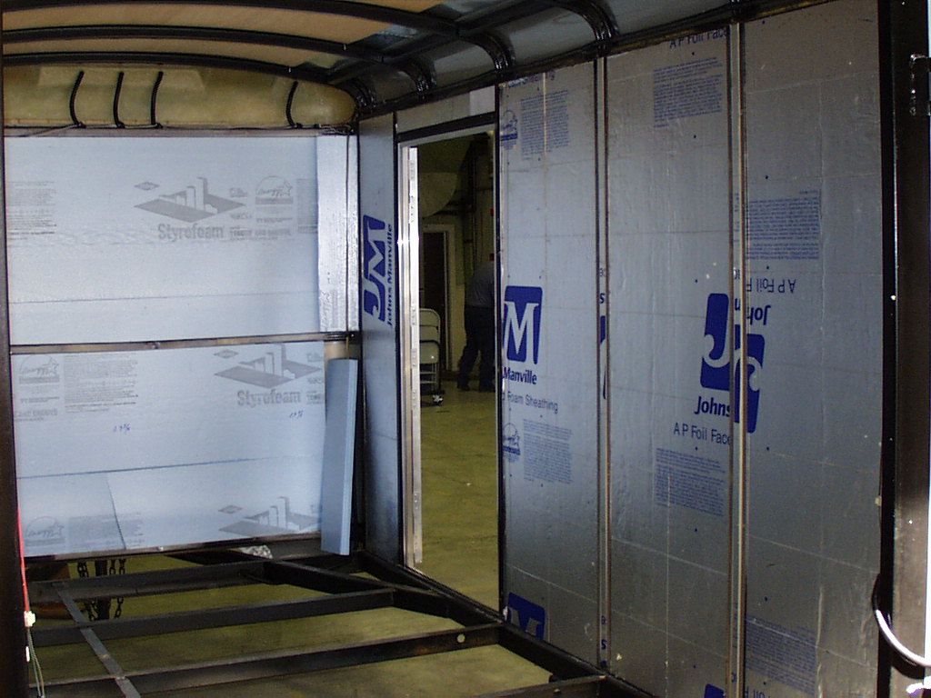
Figure 1. Inside of trailer with the floor removed and with insulation in the side and front walls. |
|
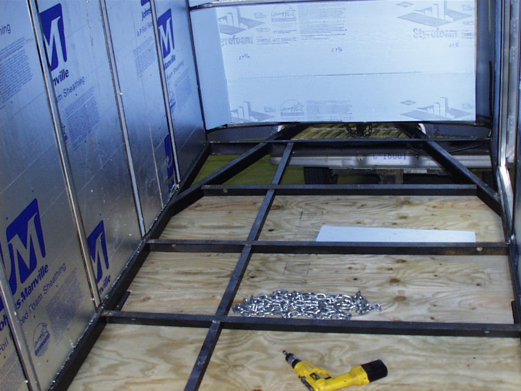
Figure 2. Inside of trailer with the subflooring partially installed. |
|
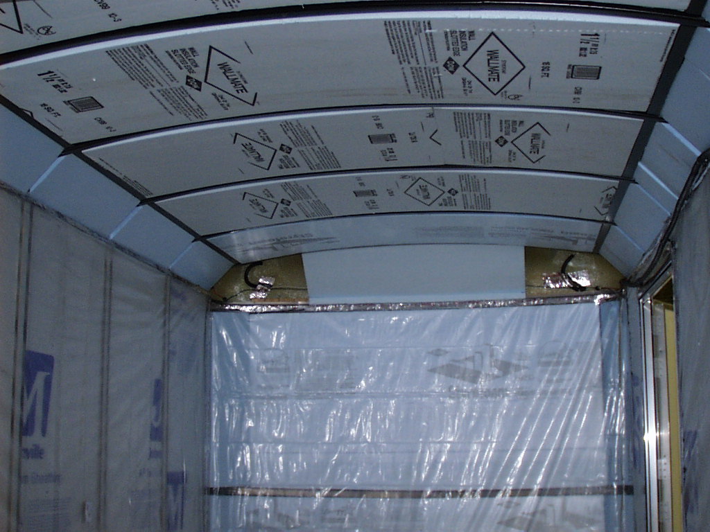
Figure 3. Side and floor insulation has been finished and the ceiling insulation is nearly completed. |
|
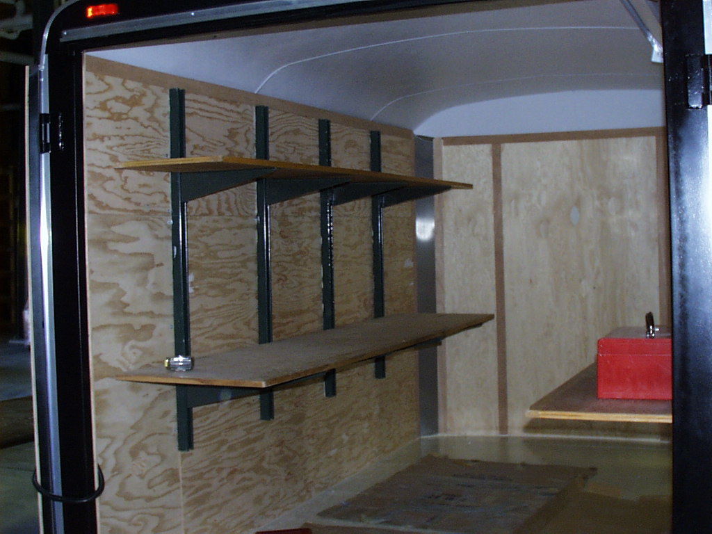
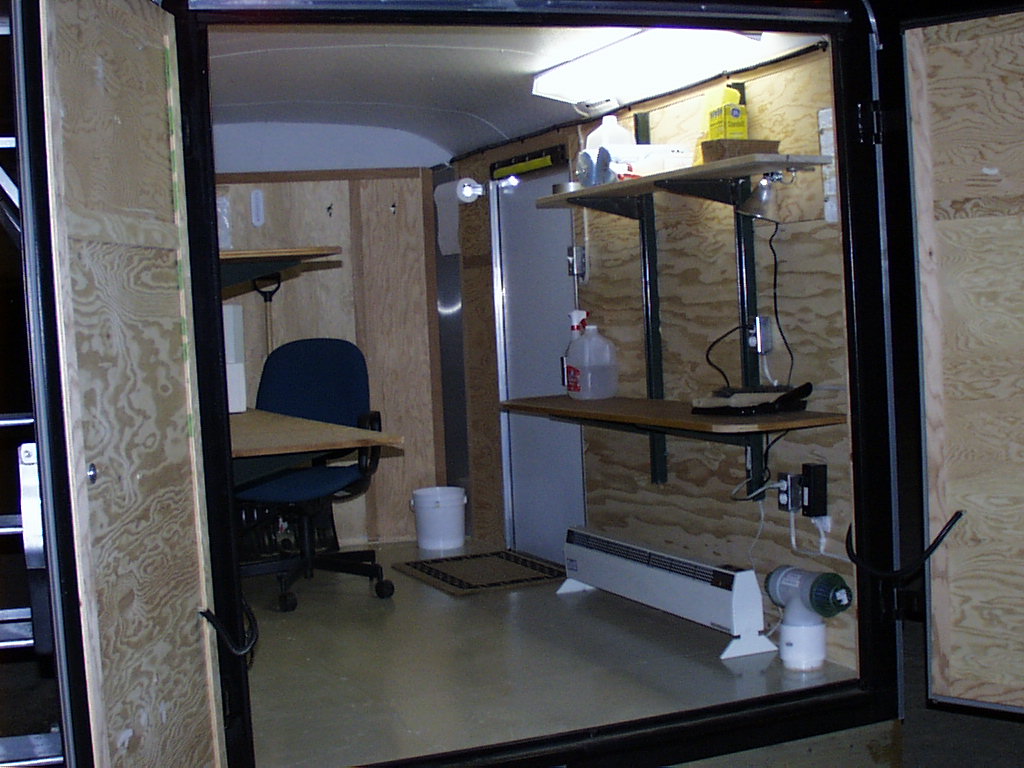
Figure 4. The insulation has been completed. Side panels have been reinstalled and ceiling has been fashioned and fit into place. Vent exhaust is located in the farthest corner. Fresh air inlet is located at the bottom right. Hole in the left side of floor is for AC and signal cable access. |
|
Figure 5. TSI platform framework. Moved to opposite side for final install. |
|
|
|
Figure 7. Four caissons in foreground. The filled trenches to the power pole and SURFRAD platform are visible. |
|
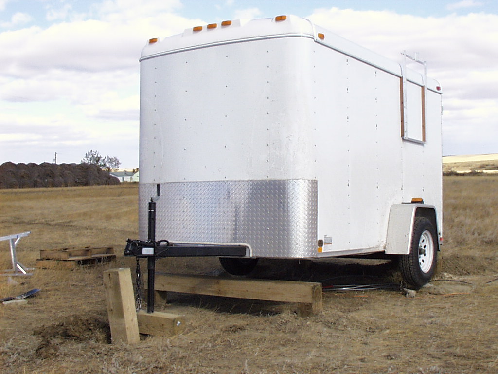
Figure 8. Trailer being moved into position. Front cross beam is in place. |
|
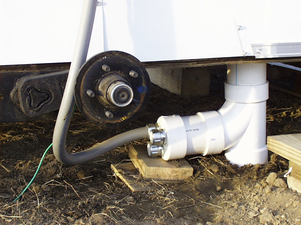
Figure 9. T-Fitting for AC and signal cable access. AC enters conduit approx. 1-foot below ground. Flexduit fittings are mounted in end cap to provide signal cable access. |
|
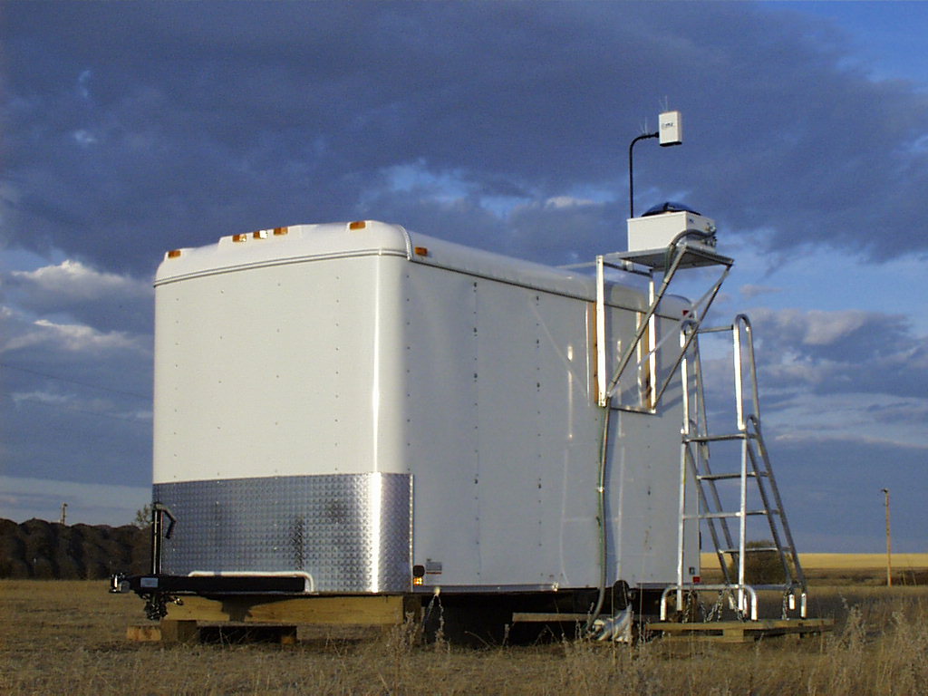
Figure 10. The completed installation. Note access steps to TSI. |
|
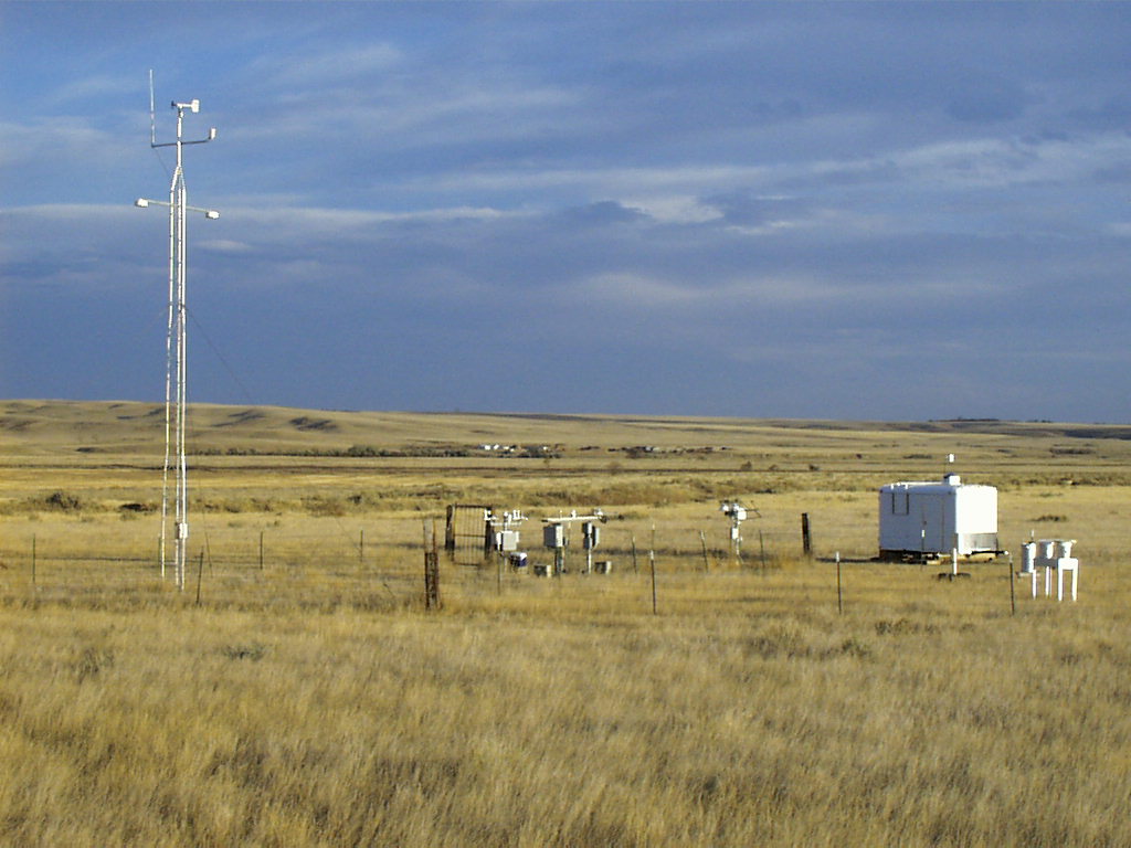
Figure 11. View of entire Fort Peck, MT, SURFRAD site. View is looking southeast. |
|
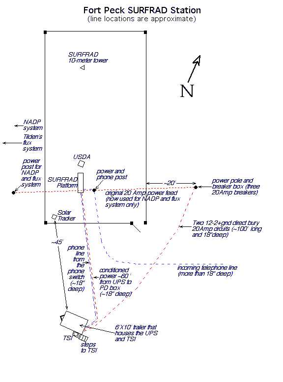
Figure 12. Schematic of Fort Peck SURFRAD site. |