
Duane Kitzis
NOAA Earth System Research Laboratory, R/GML, 325 Broadway, Boulder, CO 80305-3328
Carbon Cycle Greenhouse Gases group
and
Cooperative Institute for Research in Environmental Sciences
University of Colorado at Boulder
The GML/Global Greenhouse Gas Reference Network (GGGRN) group's methods and materials for the preparation of standard reference mixtures of trace gases in natural air are presented in detail. The standards are prepared in high pressure aluminum cylinders to calibrate trace gas measurement systems in use by GML and others participating in the Global Atmospheric Watch Program of the World Meteorological Organization (WMO/GAW). The trace gas CO2 is primarily discussed, with some mention of common processes for CO and CH4 where applicable. Cylinders are conditioned with natural air and then pressurized to 135 atmospheres using an oil free compressor. The mole fractions of CO2, CH4, CO, N2O and SF6 as well as the isotopic ratios of CO2 can be altered by spiking the cylinder with low or high concentration gas prior to filling with a balance of natural air. The air is dried to a dew point of -80°C by passing the air through a very strong desiccant. The calculations and spiking methods for CO2 are presented for targeting CO2 mole fractions to within 5 µmol/mol (often written as “ppm”). The stability of CO2 and CH4 in aluminum high-pressure cylinders is better than the present analytical precision.
High precision measurements of the trace gases CO2, CH4, and CO are being undertaken by many laboratories of various nations in order to better understand the biogeochemical cycles of these gases. There can be no integration of all these various measurement projects unless the data are all referenced to common, well defined calibration scales. The WMO has stated that the consistency required for optimally usable atmospheric CO2 measurements and comparison must be no worse than 0.1 µmol/mol for the northern hemisphere and 0.05 µmol/mol in the southern hemisphere [WMO, 1993]. Because of stringent quality controls necessary for the measurement of long-lived trace gases, stable reference gas standards are an integral part of any long-term measurement program. The Global Greenhouse Gas Reference Network group (GGGRN) of the Global Monitoring Laboratory has been involved in maintaining CO2-in-air standards since the early 1970s and over the years has expanded to include methane, carbon monoxide, the stable isotopes of CO2 and CH4, and many other trace gases. Today the standards preparation facility makes more than 300 standards per year and has enabled many laboratories worldwide to be on the same WMO CO2, CH4, and CO [Novelli et al., 1991, 1994; Dlugokencky, 2005] scales. Most of the discussion in this paper is focused on CO2.
The need for natural air standards was recognized when standards were measured using different non-dispersive infrared analyzers (NDIR). The comparative work done by Komhyr et al. [1985] was prompted by calculations of CO2 pressure broadening in nitrogen and natural air presented by others [e.g., Bischof, 1975; Griffith et al., 1982]. Because of the difference in pressure broadening of the CO2 absorption lines by nitrogen and by natural air, considerable corrections need to be applied to NDIR measurements when using CO2-in-nitrogen reference standards to calibrate CO2-in-air measurements. These corrections are strongly analyzer dependent and may not be constant in time. From these comparisons it became apparent that standards of dried whole natural air needed to be created. Efforts started in 1979 [Thoning et al, 1987] and have continued through the present. All standards are calibrated at GML in Boulder Colorado. The NOAA/GML secondary standards, to which all other NOAA standard reference mixtures are tied, were measured approximately every 3 years against the WMO designated primary standards maintained by C. D. Keeling at the Scripps Institution of Oceanography. In 1995 the WMO designated the NOAA/GML/CCGG group as the CO2 Central Calibration Laboratory. The world network is presently tied to the 15 GGGRN primary CO2 standards, now designated as the new WMO Primaries. The WMO Primary Standards are calibrated at regular intervals on our own manometric system [Zhao, 1997] and have been compared with the previous WMO calibration scale maintained at Scripps, and with a set of gravimetrically prepared primary standards at the National Institute for Environmental Sciences in Tsukuba, Japan. As of today, there appears to be no significant offset between the WMO scale and the other two scales in the range of ambient concentrations.
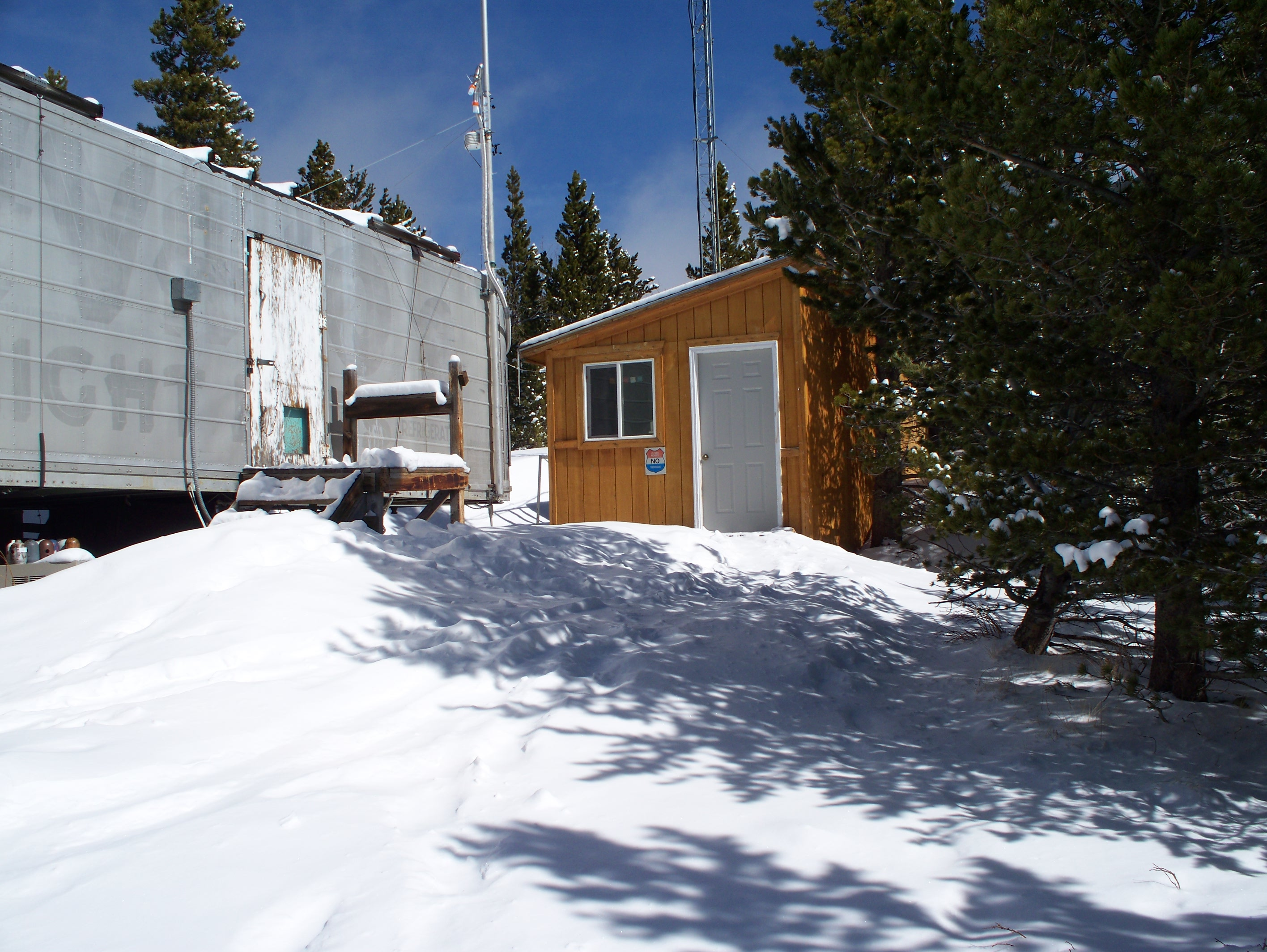
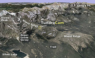
The air standard preparation facility is located in a biosphere preserve at 3040m altitude, 40° 02' N., 105° 32' W (Figure 1). This sub alpine-forested area has very limited vehicle access and usually provides non-urban continental air. The biosphere preserve is maintained by the National Forest Service and the University of Colorado's Mountain Research Station. The nearest paved road is approximately 10 km away at a much lower elevation.
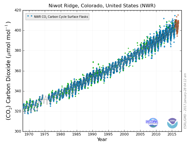
The CO2 mole fraction and its seasonal variations at the site can be approximately seen at the GML/GGGRN flask sampling network site Niwot Ridge (NWR) (Figure 2). The flask sampling site is located just to the west of the air standard preparation facility and is at 40° 03' N., 105° 35' W. at 3475 m.
Summer and winter transportation to the standards preparation site over the last 3 km varies due to snow coverage and conditions. The site is unreachable in winter except via snow-tracked vehicles or skis. To the East is the urban front range of Colorado, 25 km away. The densely populated Denver metropolitan area is 45 km to the southeast. To the south is the Arapahoe watershed, which is closed to all human traffic. To the north and west is the Arapahoe national forest and wilderness area. Basically south, west and north is very sparsely populated for 100 km or more.


In general the site experiences clean well mixed air from western North America, and beyond that from the North Pacific Ocean. The daily averaged wind speed and direction (Figure 3) shows that wind is predominantly from the west with more variable direction and weaker winds during the summer months. Some spring and summer days have short periods of local up slope easterly sourced air with a component of relatively polluted metropolitan air. This is very evident from high concentrations of correlated CO and CO2. It is common for winter winds to average 5-10 meters per second.
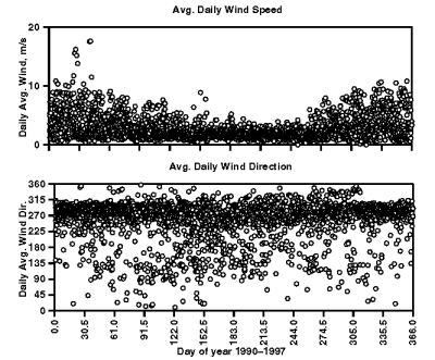

Figure 4 shows back trajectories at the filling site. These trajectories are averages from 1993 to 1997 and are divided into 6 of the most common patterns. All are predominantly from the west with spring and summer showing more continental air as compared to the longer winter trajectories.
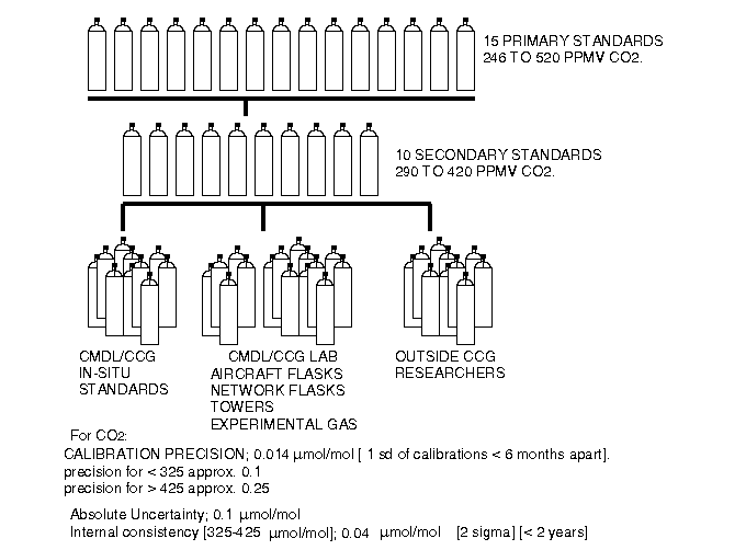
A hierarchy of the GGGRN CO2 standards is shown in Figure 5. The Central Calibration Laboratory for CO2 uses 15 Primary Standards, with a range of 246 to 520 µmol/mol. The Primaries have been measured 4 times at Scripps and 8 times on the GGGRN manometric system [Zhao, 1997]. The calibration of these standards is presently used to provide the WMO [CO2-in-air] mole fraction scale. At present, non-WMO (in house GGGRN) standards are used at CO2 mole fractions up to approximately 3000 µmol/mol to provide reference standards for the oceanographic and urban measurement community. The 18 secondaries in the range of 290 to 520 µmol/mol are calibrated relative to the Primaries. All other standards, internal and external are calibrated on a single CRDS or/and NDIR, which is referenced to these secondaries. The secondaries are typically used up in 3 to 10 years, whereas the Primaries are designed to last for many decades.
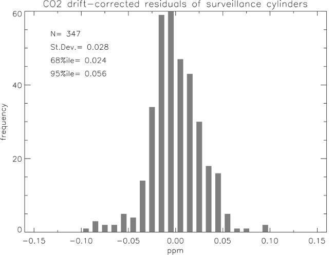
With respect to CO2 stability, the calibration histories of the various internal GML, and external collaboration, standards were checked for calibration reproducibility and long term drift. The mean difference of repeated measurements of CO2 mole fractions between 300 and 450 µmol/mol is 0.03 (Histogram of distribution, Figure 6). This is for 347 cases. Thus we can say that the reproducibility of our measurement is 0.03 µmol/mol (one sigma).
Outside of the range 300 to 520 µmole/mole is considered a non-WMO scale standard. Reproducibility was found to be 0.1 for mole fractions from 200 to 325 µmol/mol and .25 µmol/mol for mole fractions from 520 to 2500 µmol/mol. The reproducibility loss of relatively low and high CO2 mole fractions is due to the limitations of measuring toward the end of the range of the WMO scale and the slight degradation in measurement precision at high mole fractions. This estimate of reproducibility takes all cylinders into account and may contain some cases of real drift and so is a worst-case scenario.
The uncertainty stated by the CO2 calibration lab is 0.07 µmol/mol (one sigma). The reproducibilityand internal consistency of the standards in the range between 325 and 425 µmol/mol is 0.04 µmol/mol over a two-year period at the 2-sigma confidence level. If a cylinder is recalibrated at the end of its useful volume, the estimate of the stability of the calibrated value is limited by the reproducibility of our measurements (0.028 at the two sigma level), and necessary assumptions about the history of the drift, if any, between calibrations should include this uncertainty.
We use brass, pack-less, taper threaded valves in almost all cylinders with Teflon tape as the thread sealant. The Ceodeux[TM] valves have a soft seat, which does not become difficult to turn or seal over years of use. We have tested several types of cylinders, and surface treatments, and have found no evidence of specific coatings improving CO, CO2 or CH4 stability over cleaned, bare, uncoated aluminum. Luxfer aluminum, alloy 6061, cylinders with their standard cleaning preparation are the most used cylinder within the GGGRN. Luxfer, at present, provides high heat treatment, proprietary acid wash (with no etching of the surface), steam cleaning and forced air drying. The steel cylinders used in the past exhibited too much drift in CO2 mole fractions. Half of these drifts were on the order of 0.05 µmol/mol CO2 per year or more different rates or of different sign in each cylinder. Aluminum cylinders have much better stability than steel for CO and CO2. CH4 seems to be stable in any type of cylinder we use, be it aluminum, surface treated or steel, as long as the air has been dried to a low dew point. The same cylinders are used for stable CO2 isotopes and have exhibited no measurable drift [Trolier, 1996]. There have been some cases of major drift (.05 per mil 13C per week) of the CO2 stable isotopes, which were attributed to Teflon paste used as the cylinder valve sealant and also to unknown regulator contamination. There may be some evidence for long term drift of CO in aluminum cylinders as exhibited in smaller high pressure cylinders [Paul Novelli, ESRL, personal communication]. This drift however is on the order of the measurement precision and has not yet been well quantified.
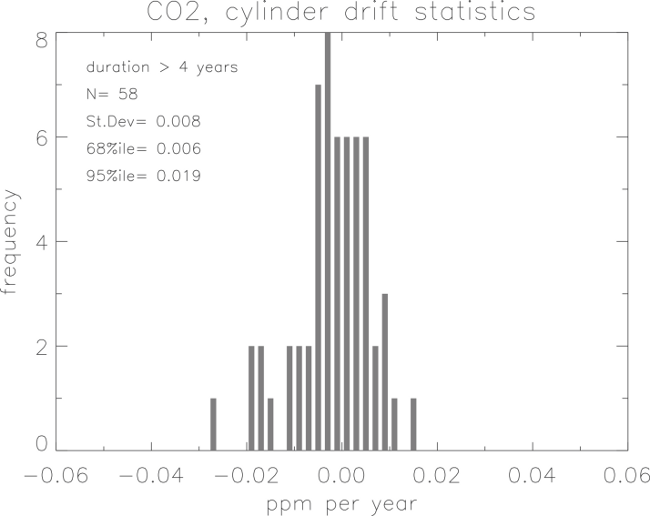
A histogram of CO2 mole fraction drift is shown in Figure 7 for 58 cylinders, which have a calibration history greater than 4 years. This shows drift in both directions. For this reason we recommend that standards be recalibrated during long use and at the end of their useful volume (pressures higher than 20 atmospheres). The drifts, as shown in the histogram, cannot presently be predicted. Drift in most of our standards is often undetectable for histories less than 2.5 years. In some documented cases, the drift has been attributed to H2O mole fractions greater than 5 µmol/mol, stainless steel valves, or valves with packing materials that preferentially absorb trace gases. There may be an increasing trend in the CO2 with decreasing cylinder pressure below 20 atmospheres. This is different in each cylinder and may not be present at all.
All Aluminum cylinders are hydro-tested after manufacturing and need to be retested periodically. All cylinders are stamped with the month and year of the last hydro-test and, if past this date, must be retested before they can be refilled and transported. Currently the period for aluminum cylinders is five years after the stamped date. In the United States hydro-testing or the more common sonic-testing can only be done by companies certified by the U. S. Department of Transportation (DOT). The sonic-testing process consists of sonic scanning the cylinder for micro cracks or imperfections.
Sonic-testing is followed by a drying /passivation process by the Scott Marrin company. After this process we have them filled with 20 atmospheres of ultra-pure(TM) air. Ultrapure air is whole air compressed at Scott Marrin and is highly filtered with mole sieves to trap most trace gases and water (Jack Marrin, Scott Marrin Inc., personal communication).
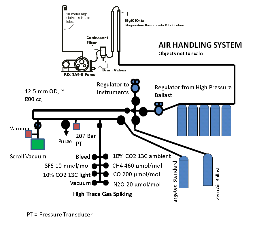
The compressor presently in service is a RIX SA6B. It is a three-stage oil-less, piston compressor commonly used for recharging Scuba tanks and is used as sold with no alterations. The three stages of compression are to 6 atm, 34 atm and 238 atmospheres respectively. The compression rings are made of filled PTFE plastic and require no lubrication. There are moisture separators between the second and third stage and at the output of the compressor. The third stage is designed with a 102 atmosphere back pressure regulator to maintain this minimum pressure against the piston. The flow at 3040 m altitude for this compressor is 126 liters per minute at ambient pressure. The temperature of the compressed air in the output-cooling coil can reach 121° Celsius. These pumps are not airtight and some alterations of trace gases may be observed. Others have made some modifications to this pump to lower the air temperature from compression and improve its use for ambient air sampling (John Mak, 1994). Some of the improvements may result in some loss of pump performance however.
The stability of many trace gases is sensitive to water vapor and especially sensitive to liquid water. Therefore the drying step is important in the preparation of any gas standards. The air exiting the compressor is passed through a Balston, 1 micron coalescent filter with a manual drain. The air then passes through 2 stainless steel tubes of 50 cm length in series. These have a 2.5 cm cross section and are filled with Anhydrous Magnesium Perchlorate ( Mg(ClO4)2 ) (Anhydrone, J T Baker). This system reduces the water vapor in the air stream to typically less than 1 µmol/mol. After approximately 52,000 liters of air has passed through the traps, the upstream trap is replaced with the downstream trap, which is replaced with a fresh one. The second moisture trap is for complete redundancy as one will dry the air stream to less than 1 µmol/mol. Water accumulated in the compressor moisture separators and the coalescent filter is blown out before and after each cylinder pressurization.
The measurement, display and control of the compressor is done with an Omega series DP205-S controller with a PX302 pressure transducer. The output solid state relay, controlled by the alarm setting, activates a set of Crydom DC control, solid state opto-isolated relays. These relays control the 220 V compressor power and is normally off unless turned on via the Omega. The setting of the control is 135 atmospheres for a full cylinder.
The pumping system is shown in Figure 8. The air is drawn through a 10 m tall, 2.5 cm diameter stainless steel intake. All high-pressure flex hoses are stainless steel braided, PTFE lined with 1/4" VCR connections. All connections are 1/4" NPT or 1/4" VCR with silver coated nickel gaskets. A meter length between the compressor and the Balston filter allows for some extra cooling of the air and therefore better condensation, before going through a coalescent filter. This was found to improve the performance of the filter significantly. All parts are secured to a rack for safety. The pop off valves and the check valve are for safety. Pop-off valves are set to 170 atmospheres on either end in case of a trap clogging, and the check valve will prevent the cylinder from dumping all the air volume in the case of a line break. 7 micron filters are in line at the end to prevent dirt from getting to the safety valve or the pressure transducer. This system can either fill 5 steel cylinders as a ballast system or directly fill the target standards. The 43.3 liter volume steel tanks can be pressurized to 238 Atm. and used to pressurize the usual 29.5 liter aluminum standards to 134 Atm. We fill aluminum cylinders of various sizes, 5.9, 15.8, 29.9, or 46.4 liters.
New standards are tested for H2O content with a MEECO Waterboy, which uses a P2O5 conductivity method and is set up to measure from 1 to 1000 µmol/mol H2O. The maximum allowable H2O mole fraction in a filled cylinder is 5 µmol/mol. Most cylinders test between 0.5-1.0 µmol/mol. This corresponds to dew points less than -75°C and usually less than -80°C when expanded, and less than -30°C under full pressure.
When a cylinder is to be refilled and contains air with the trace gases near ambient, conditioning is not usually necessary. New cylinders have ultra-pure (TM Scott Marrin Inc.) air and cylinders with undesirable concentrations left in them must be purged of the old air to have the walls conditioned to ambient air. Drifts have been observed, due to evacuating the cylinder before filling, which have persisted for months. Drifts due to spiking, discussed below, have been eliminated by filling the cylinder immediately after spiking. There is no evidence to show drifting due to the filling process described below. As a result of these experiences and to remain conservative about long-term effects we do not know about yet, the following steps have been adopted by GGGRN as procedure;
From this flushing procedure the original air left in the cylinder is less than .01 % of the volume at the time of spiking and less than 5E-5 % after the final filling. Drifts in the stable isotopes of CO2 have been observed, even after this procedure, and have stabilized over time.
The 33 atmospheres of air is blown down to ambient pressure. The standard can now be filled with ambient air or the trace gas can be adjusted via one of the next two steps. The cylinders are filled to 136 atmospheres in about 45 minutes.
Trace gas increase = K * (Target mole fraction - Ambient mole fraction)
Where K is a constant for trace gas increase/ pressure of the spiking gas in the transfer volume.
The over pressures we use in the transfer volume are on the order of 0.1 atm. of over pressure per increased µmol/mol CO2 in a standard 29.5 l. cylinder. Because the composition of the spiking gas varies, this value varies and must be found empirically with each cylinder of spike gas. Once a few cylinders are spiked and calibrated the constant K is the same over a wide range of increased trace gases. Examples of spike gas mole fractions are 10 % CO2 in air, 1.5 % CO in air and 2.5% CH4 in air.
The pressures we use in the transfer volume are on the order of 0.1 to 20 atm. spike gas for increasing a given analyte final concentration in a 29.5 liter cylinder. Because the composition of the spiking gas varies, this value of K varies and must be found empirically with each new cylinder of spike gas. Once a few standards are spiked and calibrated the constant K is the same over a wide range of increased trace gases. Examples of spike gas mole fractions are 10 % CO2 in air, 200 µmol/mol CO in air and 460 µmol/mol CH4 in air. Similar spike gases include N2O, SF6, 0 ‰ 13CO2, -9 ‰ CO2, -35 ‰ CO2. The isotopes of CO2 can be manipulated with mixtures composed of light or heavy CO2. There are also 1000 and 2000 µmol/mol CO2 mixtures, with relatively increased CH4, CO or/and N2O in the same spike tank for increasing small volume (2 to 5 liter) calibration flasks above ambient for some special project applications.
Lowering a trace gas below ambient levels requires that some volume of air with none of the trace gas be put in the cylinder.
Pf * Vf = Pz * Vz + Pa * Va
Where
Pf is the final filling pressure of the standard at room temperatureThe zero air is purchased from Scott Marrin as UP-air (CO2, CH4, CO free air) or CryoUP-air (also N2O and SF6 almost zero concentration). The zero air is put directly into the cylinder for below ambient targeted final mole fractions. The necessary partial pressure of the zero gas is calculated from the above formula, re-written as follows;
Pf * Vf = [Pf - Pz] * Va
Pf * [Va - Vf] / Va = Pz
The standard cylinder is filled to the pressure P(z) from the ballast whole air (with the specific trace gas removed) and then filled to the final pressure with dry natural air of ambient mole fractions.
Occasionally, the targeted concentration is missed by an amount, which requires adjustment. If the mole fraction of the standard is closer to ambient than the target concentration, it is easiest to blow this off and start over. Experimenting with introducing small volumes of high pressure (high or low mole fractions) into the air stream have proven very time consuming due to the time necessary for the cylinder to become evenly mixed before obtaining a usable measurement from the standard.
If, however the final mole fraction turns out to be farther away from ambient than the desired targeted trace gas mole fraction, it is possible to adjust the standard toward the desired concentration. The same partial pressure formula above can be used, adding a term for the gas already in the cylinder and blowing the cylinder down to the necessary partial pressure. When the cylinder is filled to the final pressure again, with ambient levels of the trace gas the mole fraction will be adjusted toward the targeted value fairly precisely.
In the case where the mole fraction in the cylinder is too low and must be increased;
Pf * [Va - Vf] / [Va - Vm] = Pm
where Vm is the mole fraction of the gas in the cylinder, and Pm is the pressure to lower the standard to, before refilling with ambient air.
In the case where the mole fraction in the cylinder is too high and can be lowered;
Pf * [Vf - Va] / [Vm - Va] = Pm
After the standard has been filled it is transported to the WMO Central Calibration Laboratory in Boulder, CO. The standard is then calibrated three times with approximately one week intervals between each calibration. For CO2 these measurements are done by comparing them to secondary GML standards that are closely tied to the primary WMO standards. The trace gas mole fraction reported includes measurement reproducibility as well as a check on cylinder stability. These standards are used at our base line observatories, by international collaborative projects and by many national laboratories as tertiary standards. There is evidence that, as the volume of pressurized air is used up, the trace gas can come off the walls in disproportionate amounts. This has sometimes been seen in cylinders with CO2, when a standard is used at pressures below 20 atm. The CO2 mole fraction may increase with pressure loss. This effect is variable and may not be measurable in all tanks. Also, when air is used from the cylinder at a high flow rate, the cylinder head may cool which could produce drift. To make sure we can get a representative final calibration we discontinue use when the cylinder pressure becomes lower than 20 atm.